
Standard Rating Test Conditions for Refrigeration & HVAC Systems: Engineering Guide
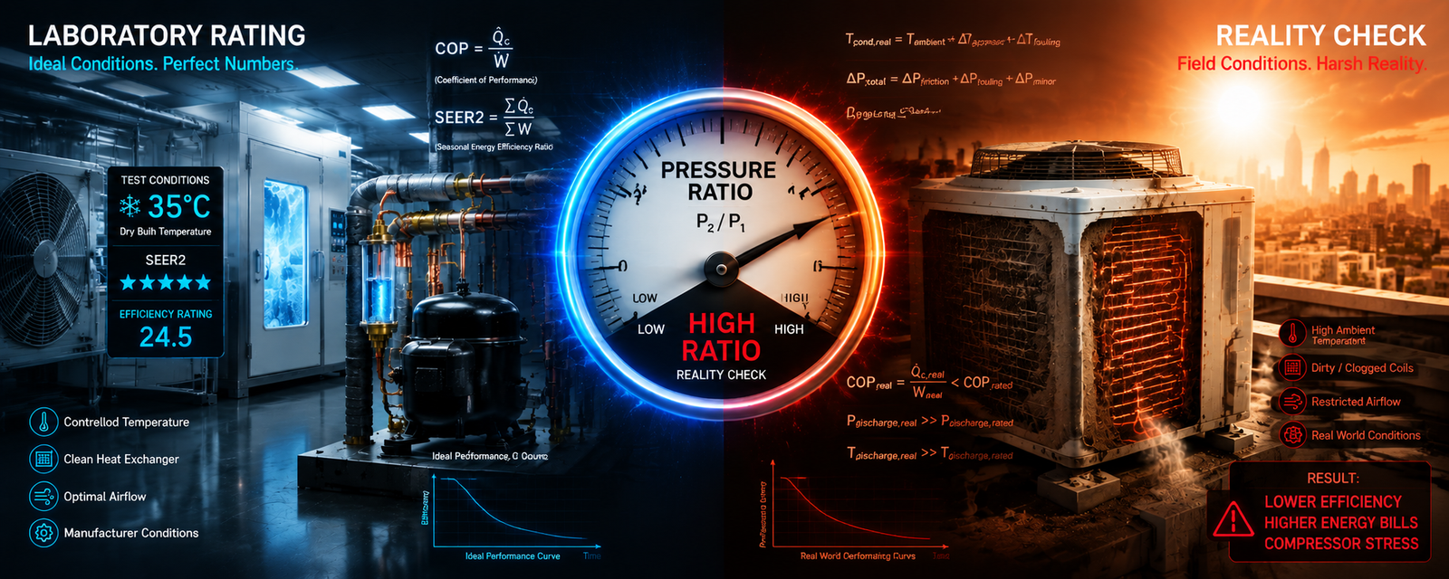
Standard Rating Test Conditions for Refrigeration & HVAC Systems: Engineering Guide
Executive Summary
In refrigeration and air conditioning systems, cooling capacity (Watts or BTU/hr) and efficiency metrics (COP, EER2, SEER2) are not static physical constants. They are direct thermodynamic functions of the operating pressure ratio, evaporating temperature (Te), condensing temperature (Tc), subcooling, and return gas superheat. Standard test conditions establish universal laboratory benchmarks that enable normalized component sizing, fair manufacturer benchmarking, and regulatory energy certification. Understanding how laboratory rating conditions differ from real-world field conditions prevents catastrophic undersizing, compressor overheating, and premature system failure.
1. What Are Standard Test Conditions?
A Standard Rating Test Condition is a standardized set of thermodynamic parameters used in a controlled calorimeter or psychrometric test room to determine the baseline performance of compressors, condensing units, and complete heat pump/AC systems. Because moving the evaporating temperature higher increases cooling capacity while raising condensing temperature decreases it, a capacity figure (e.g., "190 Watts" or "36,000 BTU/hr") is scientifically meaningless without its associated rating standard.
Core Thermodynamic Control Parameters
- Evaporating Temperature (Te / Saturated Suction Temperature): The boiling point of refrigerant in the evaporator coil, determining the cooling cabinet temperature.
- Condensing Temperature (Tc / Saturated Discharge Temperature): The condensation temperature in the condenser coil, dictating heat rejection against ambient air.
- Suction Return Gas Temperature: The temperature of superheated vapor entering the compressor suction port (typically 32.2°C / 90°F under ASHRAE).
- Liquid Subcooling Temperature: The temperature of liquid entering the expansion device (determines net refrigeration effect).
- Ambient Temperature: External air surrounding the compressor shell and condenser coil.
2. Hermetic Compressor Test Standards: ASHRAE vs. EN 12900 / CECOMAF
In domestic refrigerators and commercial reach-in freezers, compressors are rated across three primary application envelopes: LBP (Low Back Pressure), MBP (Medium Back Pressure), and HBP (High Back Pressure). Below is the direct comparison of standard laboratory rating parameters:
| Standard Name | Application Class | Evap Temp (Te) | Cond Temp (Tc) | Return Gas Temp | Liquid Subcooling | Primary Use Case |
|---|---|---|---|---|---|---|
| ASHRAE LBP | Low Back Pressure | -23.3°C (-10°F) | 54.4°C (130°F) | 32.2°C (90°F) | 32.2°C (22.2K Subcool) | Household freezers, deep-freeze cabinets, French door ice sections. |
| EN 12900 / CECOMAF LBP | Low Back Pressure | -25.0°C (-13°F) | 55.0°C (131°F) | 20.0°C (68°F) | 55.0°C (0K Subcool) | European standard domestic and light commercial refrigeration. |
| ASHRAE MBP | Medium Back Pressure | -6.7°C (20°F) | 54.4°C (130°F) | 35.0°C (95°F) | 46.1°C (8.3K Subcool) | Beverage merchandisers, fresh food display cases, commercial coolers. |
| ASHRAE HBP | High Back Pressure | +7.2°C (45°F) | 54.4°C (130°F) | 35.0°C (95°F) | 46.1°C (8.3K Subcool) | Dehumidifiers, packaged room air conditioners, high-temp fluid chillers. |
Critical Engineering Note: The same compressor tested under ASHRAE LBP will report approximately 10% to 15% higher nominal cooling capacity than under EN 12900 LBP because ASHRAE utilizes a higher liquid subcooling credit (32.2°C liquid vs. 55°C saturated liquid).
Select a target application to review standardized reference points and operating limits.
Reference baseline: ASHRAE Standard 23, AHRI 210/240-2024, and ISO 5151.
3. Residential & Commercial Air Conditioning: AHRI 210/240 & DOE SEER2
Under the US Department of Energy (DOE 10 CFR 430 Appendix M1) and AHRI Standard 210/240, central air conditioners and air-source heat pumps are evaluated across specific test points to calculate seasonal efficiency ratings (SEER2 and HSPF2):
| AHRI Test Point | Operational Mode | Indoor Air Temp (DB / WB) | Outdoor Ambient Temp (DB / WB) | Compressor Speed / Load |
|---|---|---|---|---|
| A_Full (Standard Rating) | Cooling Full Load | 80.0°F (26.7°C) / 67.0°F (19.4°C) | 95.0°F (35.0°C) / 75.0°F (23.9°C) | 100% Full Capacity (EER2 baseline) |
| B_Full / B_Low | Cooling Intermediate | 80.0°F (26.7°C) / 67.0°F (19.4°C) | 82.0°F (27.8°C) / 65.0°F (18.3°C) | Part-Load / Minimum Speed Stage |
| H1_Full / H1_Low | Heating High Ambient | 70.0°F (21.1°C) / 60.0°F (15.6°C) | 47.0°F (8.3°C) / 43.0°F (6.1°C) | Standard Heating Rating Point |
| H2_Full (Frost Region) | Heating Cyclic Defrost | 70.0°F (21.1°C) / 60.0°F (15.6°C) | 35.0°F (1.7°C) / 33.0°F (0.6°C) | Active Frosting & Defrost Evaluation |
| H3_Full / H4_Low | Low-Temp Heating | 70.0°F (21.1°C) / 60.0°F (15.6°C) | 17.0°F (-8.3°C) to 5.0°F (-15.0°C) | Cold-Climate Heat Pump Capacity Verification |
4. Laboratory Rating Standards vs. Real-World Field Conditions
Standard test conditions provide repeatable regulatory metrics, but technicians and engineers must account for real-world environmental deviations:
| Operational Variable | Standard Lab Rating Benchmark | Real-World Field Conditions | Engineering & Performance Impact |
|---|---|---|---|
| Outdoor High Ambient | 95°F (35°C) Standard Dry Bulb | 105°F to 120°F (40°C–49°C) Rooftop/Desert | Capacity derates by 15% to 30%; discharge pressure spikes; thermal lockout risk increases. |
| Duct Static Pressure | 0.50 in. w.g. ESP (SEER2 test standard) | 0.70 to 1.10 in. w.g. (Restricted residential ducts) | Airflow drops from 400 to <320 CFM/ton; coil freezes; blower motor wattage increases significantly. |
| Sensible Heat Ratio (SHR) | 0.72 – 0.80 SHR (Standard 50% RH) | 0.60 – 0.70 SHR (Humid Coastal Zones) | High-sensible equipment satisfies thermostat too quickly without removing sufficient latent humidity. |
| Electrical Grid Frequency | 50 Hz (2,900 RPM) or 60 Hz (3,500 RPM) | Voltage sag under peak grid demand | Running a 50Hz rated compressor on 60Hz increases mass flow by ~20% but increases motor winding temperature. |
5. Engineering Selection & Diagnostic Decision Framework
When selecting replacement components (compressors, metering devices, inverters) or verifying field performance, execute this 4-step protocol:
Never install an HBP compressor into a low-temperature freezer application. LBP motors feature high-torque starting windings and smaller displacement cylinders optimized for high pressure ratios (Pc / Pe > 8). Installing an HBP compressor in an LBP application causes motor stalling and thermal overload trips.
When comparing datasheets between suppliers, ensure both ratings cite the exact same standard. Convert EN 12900 figures to ASHRAE LBP before calculating refrigeration pull-down loads to avoid under-sizing refrigerated cabinets by 10–15%.
Calculate volumetric displacement (Vd = cc/rev) rather than relying on nominal fractional horsepower labels ("1/4 HP" or "1/3 HP"). Confirm motor winding voltage and line frequency (115V 60Hz vs. 230V 50Hz) to ensure motor insulation and current ratings are preserved under peak summer ambient conditions.
When charging or servicing equipment in the field, calculate target superheat (for fixed orifice/capillary systems) or target subcooling (for TXV/EEV systems) using manufacturer charging charts adjusted for actual indoor wet-bulb and outdoor dry-bulb temperatures, rather than nominal 95°F/80°F AHRI defaults.
HVAC-R Technical Support & Engineering Verification
Compressor Cross-Reference
Verify displacement, test standard capacity, and inverter protocol match.
Track Existing Order
Real-time carrier tracking and shipping updates for replacement parts.
365-Day Return Guarantee
All certified refrigeration components covered under full replacement warranty.