

Diagnostic Summary
Embraco Fullmotion variable-speed compressors utilize a dedicated external inverter drive (such as the VCC3 series) to convert 120V AC household line power into 3-phase variable frequency AC (53 to 150 Hz) for high-efficiency brushless DC motors. When the refrigerator fails to cool despite active interior fans, the failure is most frequently caused by a blown inverter drive module. To ensure proper operation, replacement inverters must match two mandatory parameters: Inlet Voltage (100–127V vs. 220–230V) and Control Signal Protocol (Frequency/PWM vs. Drop-in/Thermostat).
Never, under any circumstances, attempt to energize an Embraco Fullmotion variable speed compressor with direct line voltage from the electrical network (“direct start” or test cord bypass). Applying direct 120V/240V AC to the 3-phase hermetic terminals will permanently destroy the compressor motor windings. Always disconnect the refrigerator power cord and wait at least 30 seconds for internal electrolytic capacitors to discharge before servicing electrical terminals.
1. Identify Voltage & Control Signal Parameters
Before ordering or installing a replacement inverter, inspect the data label on your original unit to identify its Inlet Voltage and Embraco Part Number.
| Universal Part Code | Inlet Voltage (V) | Control Signal Type | Application Scope |
|---|---|---|---|
| 519308328 / W10710090 | 100–127V AC (50/60 Hz) | Frequency (PWM) | Standard North American variable speed models (Whirlpool, KitchenAid, Maytag, GE). |
| 519308329 | 100–127V AC (50/60 Hz) | Drop-in (Thermostat ON/OFF) | Mechanical thermostat or relay-switched 120V systems. |
| 519308330 | 220–230V AC (50/60 Hz) | Frequency (PWM) | International / European frequency-controlled models. |
| 519308331 | 220–230V AC (50/60 Hz) | Drop-in (Thermostat ON/OFF) | International / European standard drop-in units. |
Compatibility Note: Universal Embraco aftermarket inverters are not compatible with Liebherr brand refrigerators utilizing proprietary serial bus protocols.
Enter your original inverter code (e.g. 519306007, 519306008, VCC3 1156, VCC3 2456, or Refrigerator Model #) to verify exact replacement match.
Cross-references over 120+ original Embraco factory part codes and 2,500+ French Door refrigerator platforms.
2. Symptoms & Diagnostic Testing Matrix
Follow this systematic electrical diagnostic sequence in the machine compartment before removing the old inverter board:
| Suspect Component | Failure Probability | Observed Symptom | Field Test Procedure |
|---|---|---|---|
| Embraco Inverter Board (VCC3) | 70% | 120V AC power and 4–6V DC frequency signal present, but compressor does not start, clicks repeatedly, or shuts down after 3 seconds. | Measure 120V AC across Line & Neutral; verify 4–6V DC PWM signal across communication terminals. If inputs are verified and compressor windings are balanced, the inverter is defective. |
| Compressor Winding Failure | 20% | Inverter attempts startup; compressor shell becomes extremely hot or trips on thermal overload. | Disconnect 3-pin hermetic plug. Measure resistance between all terminal pin pairs (1-2, 2-3, 1-3). All three readings must measure balanced between 6.0 Ω and 10.0 Ω with zero continuity to chassis ground. |
| Main Control Board (Signal Loss) | 10% | Both refrigerator and freezer compartments warm; inverter receives 120V AC input but 0V DC control signal. | Measure DC voltage on the 2-wire signal cable (2) from the main control board during active cooling demand. |
3. Repair Cost Analysis: DIY vs. Professional Technician
Replacing an external Embraco inverter control board does not require tapping the sealed refrigerant loop or brazing copper lines. Review the cost breakdown below:
| Expense Category | Professional In-Home Service | DIY In-House Replacement |
|---|---|---|
| Trip Charge / Diagnostic Fee | $100.00 – $150.00 | $0.00 |
| Labor Rate (1.0 to 1.5 Hours) | $150.00 – $220.00 | $0.00 (20–30 mins DIY) |
| Inverter Board Retail Price Markup | $200.00 – $280.00 | $112.99 (Factory Direct) |
| Total Estimated Expense | $450.00 – $650.00 | $112.99 |
| Resolution Lead Time | 4 to 8 business days | Same Day Dispatch / 30 Min Fix |
4. Required Certified Replacement Inverter
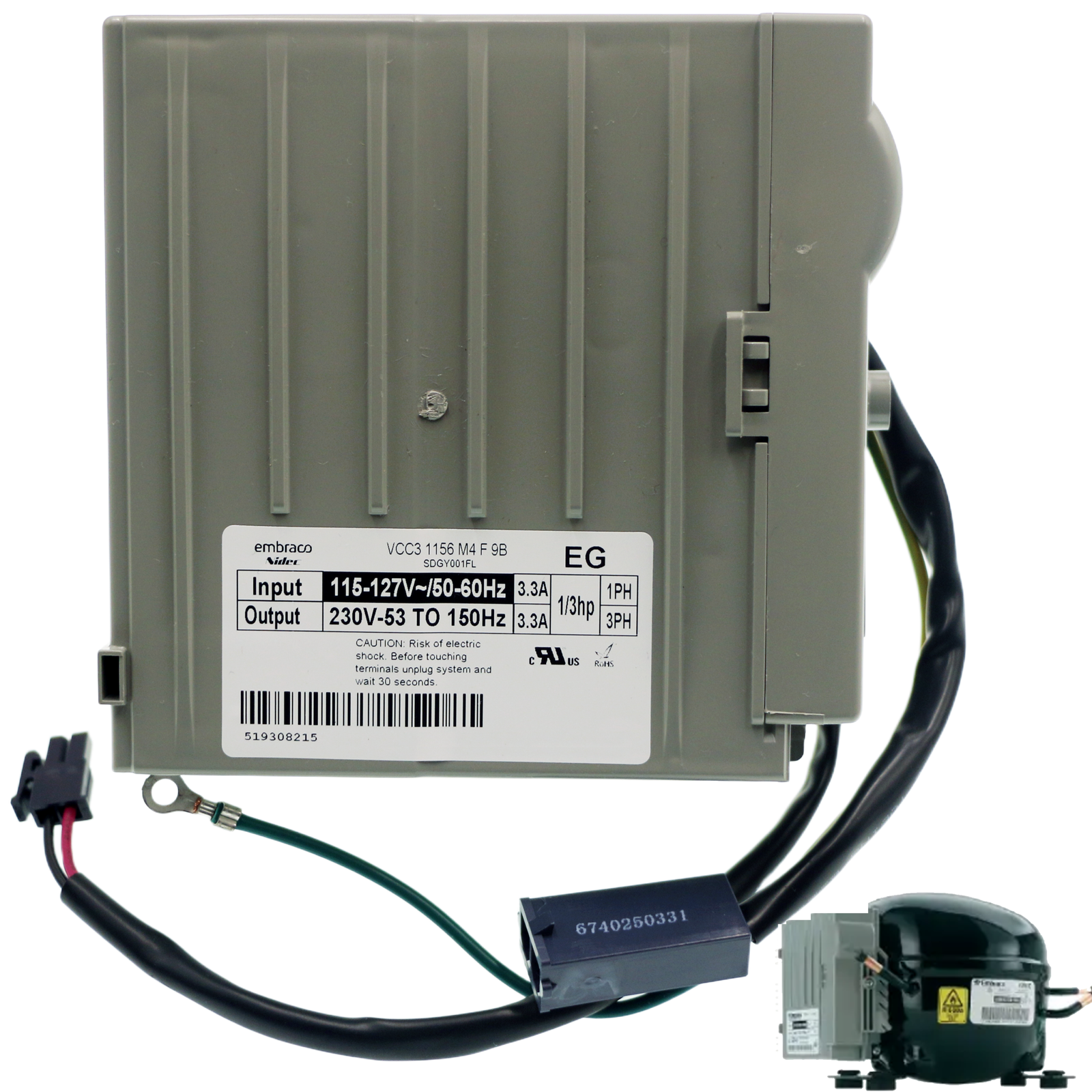
Embraco VCC3 Refrigerator Inverter Control Board (3.3A / 115V–127V Frequency)
Cross-Reference / Replaces: 519308328, 519306007, 519306008, 519306010, 519306022, W10710090, VCC3 1156, VCC3 2456, W10312695, AP5956760, PS10064063.
Guaranteed Fit: Whirlpool WRF736, WRF989, KitchenAid KRFC300, KRFF305, Maytag MFI2570, MFW2055, and Kenmore 596-series refrigerators.
- Direct replacement for Embraco VCC3 3.3A inverter control boards
- Matches 115V–127V input and 53–150Hz variable frequency output
- Pre-calibrated 3.3A frequency protocol for easier installation
- Cross-references W10710090, W10312695 and Embraco VCC3 series
5. Step-by-Step Replacement Instructions (Per Embraco Service Manual)
Required Tools
- 1/4-inch hex nut driver or magnetic socket
- Phillips head screwdriver
- Small flathead screwdriver (to release locking tabs)
- Digital multimeter with needle probes
- Work gloves and safety glasses
Part 1: Removing the Defective Inverter
Unplug the refrigerator from the wall electrical outlet. Wait at least 30 seconds before opening the machine compartment or touching internal wiring to ensure full capacitor bleed-off.
Remove the lower rear metal access panel using a 1/4″ nut driver. Locate the inverter control box mounted adjacent to or directly on the compressor. Unscrew and remove the side connection cover to access internal terminals.
Carefully disconnect the three primary cable connections:
- Cable 1 (Power Supply): Depress the locking tab on the 120V AC 2-pin line power connector and pull it free.
- Cable 2 (Control Signal): Disengage the small 2-pin low-voltage signal cable from the main PCB.
- Cable 3 (Grounding): Remove the ground screw securing the green/yellow grounding ring terminal to the chassis.
Disconnect the 3-pin compressor cable from the hermetic terminal pins on the compressor bell housing. Release the inverter from its mounting fastening points or compressor bracket and remove it from the cabinet.
Part 2: Installing the New Embraco Inverter
Position the new inverter onto the compressor mounting plate or chassis fastening points. If the replacement is arranged in the cabinet rather than directly mounted, ensure it is securely fastened so it does not shift or vibrate during operation.
Connect the 3-prong compressor cable firmly onto the compressor’s hermetic terminal pins. Ensure full mechanical engagement to prevent terminal arcing.
Inside the inverter connection bay:
- Plug in Power Supply Cable (1) until the locking latch clicks.
- Plug in Signal Cable (2) securely.
- Fasten Grounding Cable (3) to the grounding terminal screw.
Route all wiring neatly through the designated inverter wire channels to prevent pinching. Reinstall the inverter side access cover and tighten the retaining screw. Reattach the refrigerator rear metal access panel.
6. Post-Installation Testing & Verification
To verify proper variable-speed inverter operation:
- Restore Power: Plug the refrigerator power cord into the 120V outlet.
- Relay & Fan Engagement: Within 15–45 seconds, listen for the inverter module’s startup sequence and verify the condenser fan motor begins spinning.
- Smooth Frequency Ramp: The variable speed compressor will start at its baseline speed (~1,600 RPM) and smoothly accelerate to higher operational frequencies (~3,000–3,600 RPM) as required by the cooling demand.
- Thermal Check: Within 10–15 minutes, confirm that the compressor discharge tube becomes warm to the touch and frost begins forming uniformly across the freezer evaporator coils.