
Diagnostic Summary
When a refrigerator stops cooling in both compartments while interior lights and evaporator fans run, the primary cause is an inoperative variable-speed compressor. In refrigerators equipped with Embraco VCC3 systems, the inverter module converts 120V AC household power into 3-phase variable frequency DC power. A failed inverter control board (Part # W10710090) causes the compressor to remain idle, click repeatedly, or hum for 3 to 5 seconds before shutting down on internal thermal overload. Replacing this external module restores active cooling without opening the sealed refrigerant system.
1. Verify Refrigerator Model Compatibility
To confirm whether your refrigerator uses the Embraco VCC3 inverter control board, locate the full model number from the factory rating plate inside the cabinet.
- French Door Models: Located on the upper left interior cabinet wall of the fresh food section.
- Side-by-Side Models: Located on the upper right sidewall or ceiling liner near the water filter compartment.
Enter your appliance model number to verify direct fitment for Inverter Board W10710090 (VCC3 3.3A).
Database supports over 1,800+ Whirlpool, KitchenAid, Maytag, and Kenmore French Door platforms.
2. Symptoms & Electrical Diagnostic Procedure
| Suspect Component | Failure Rate | Observed Symptom | Multimeter Verification Step |
|---|---|---|---|
| Inverter Control Board (W10710090) | 70% | 120V AC input present and 4–6V DC signal received, but compressor fails to start or buzzes briefly. | Test 120V AC between L & N terminals; test 4–6V DC across communication signal pins. If inputs are valid and windings are balanced, the inverter board has failed. |
| Compressor Locked Rotor / Open Winding | 20% | Inverter board clicks and attempts start; compressor gets extremely hot or draws excessive locked-rotor current. | Disconnect 3-pin compressor plug. Measure resistance across all 3 pin combinations (1-2, 2-3, 1-3). Readings must be balanced between 6.0 Ω and 10.0 Ω with zero continuity to ground. |
| Main Control Board (Low Signal) | 10% | Both compartments warm; inverter receives 120V AC power but 0V DC communication command. | Measure DC voltage on the 2-pin low-voltage harness connector from the main PCB. If 0V DC is measured during active cooling demand, inspect the main control board. |
Multimeter Diagnostic Steps
- Line Voltage Check: Set multimeter to AC Volts. Probe the 120V supply connector at the inverter (110V–125V AC normal).
- Control Signal Check: Set multimeter to DC Volts. Probe the 2 communication wires from the main board (4V–6V DC frequency signal normal during cooling calls).
- Compressor Winding Resistance: Disconnect inverter from 3-pin compressor header. Set multimeter to Rx1. Test Pin 1-2, 2-3, 1-3 (must be balanced between 6.0 Ω and 10.0 Ω).
3. Repair Cost Analysis: DIY vs. Professional Service
| Cost Component | Professional Service Call | DIY In-House Replacement |
|---|---|---|
| Diagnostic / Dispatch Fee | $100.00 – $150.00 | $0.00 |
| Labor Charges (Standard Hourly) | $150.00 – $220.00 | $0.00 (20–30 mins DIY) |
| Inverter Board Retail Price Markup | $200.00 – $280.00 | $89.99 (Direct Replacement) |
| Total Estimated Expense | $450.00 – $650.00 | $89.99 |
| Turnaround Timeline | 3 to 8 business days | Same Day Dispatch / 30 Min Fix |
4. Required OEM Replacement Inverter Board
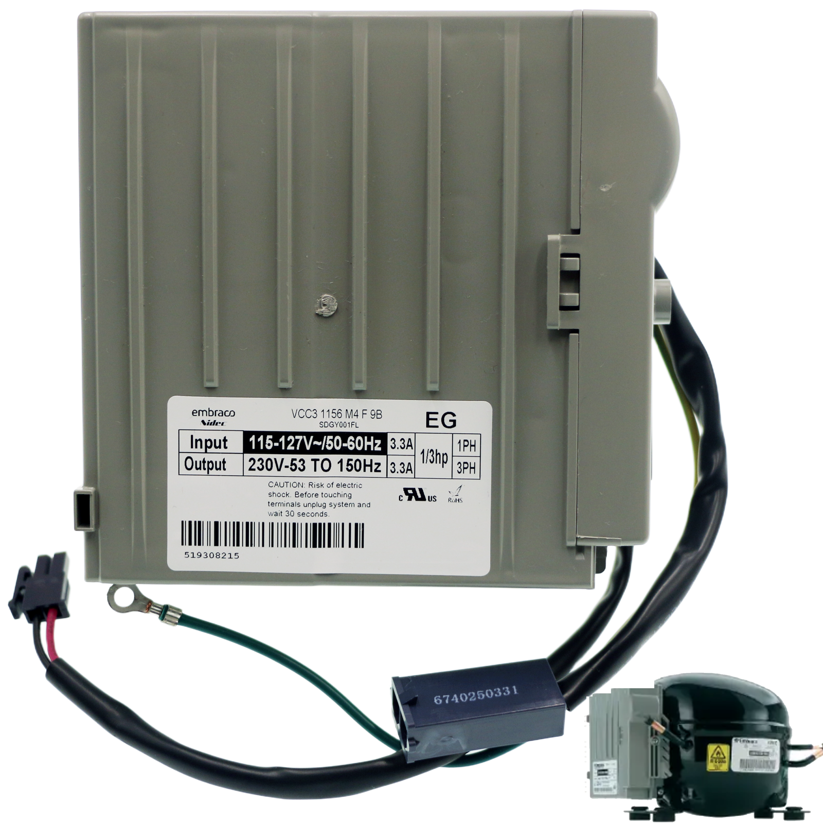
W10710090 Refrigerator Inverter Control Board (Embraco VCC3 3.3A)
Cross-Reference / Replaces: VCC3 2456, W10312695, 3447144, AP5956760, PS10064063, EAP10064063.
Guaranteed Fit: Whirlpool WRF736SDAM, WRF989SDAM, KitchenAid KRFC300ESS, KRFF305ESS, Maytag MFI2570FEZ, MFW2055FRZ, and Kenmore 596-series refrigerators.
- ✓ 365-Day Hassle-Free Returns
- ✓ Factory Pre-Calibrated 3.3A Output
- ✓ 1-Year Comprehensive Replacement Warranty
5. Step-by-Step Replacement Instructions
Required Tools
- 1/4-inch hex nut driver or socket
- Small flathead screwdriver
- Digital multimeter with needle probes
- Work gloves and safety glasses
Pull the refrigerator forward. Unplug the power cord. Use a 1/4″ nut driver to remove the lower rear sheet metal access cover.
Locate the black/grey inverter control box mounted onto the side of the Embraco compressor bell housing.
Release the 120V AC input power connector locking clip and pull it free. Release the 2-pin low-voltage DC communication harness. Remove the green ground screw.
Release the plastic retaining clip on the inverter housing and pull outward to disconnect its female 3-prong terminal from the compressor pins.
Align the 3-pin receptacle of the new board with compressor terminals. Push firmly until fully seated. Snap the mounting bracket into the retaining slot.
Reattach ground wire. Plug in 120V AC and low-voltage communication connectors until locking tabs click. Reinstall rear metal panel.
6. Testing & System Verification
- Power Restoration: Plug power cord into 120V outlet.
- Inverter Relay Engagement: Within 15–45 seconds, listen for a soft click followed by condenser fan activation.
- Compressor Frequency Ramp-Up: The compressor will start at low frequency (~1,600 RPM) and smoothly ramp to high speed (~3,000–3,600 RPM).
- Thermal Check: Within 10–15 minutes, touch the compressor discharge line (it should warm up) and check for frost on freezer evaporator coils.