
Diagnostic Summary
When a Whirlpool, Maytag, or Kenmore top-load washing machine fails to start, exhibits an unresponsive control interface, stalls mid-cycle, or repeatedly logs error codes such as F0E2 (oversuds), F5E1 (lid lock failure), or F7E1 (motor tachometer speed sensing), the failure is commonly traced to blown switching relays, an onboard microcontroller malfunction, or a damaged analog pressure transducer on the main electronic control board (W11176140). Replacing this central control unit restores full cycle logic, motor speed control, and water level management.
1. Verify Washer Model Compatibility
Whirlpool produces multiple control board revisions across its Vertical Modular Washer (VMW) platform. To verify that part W11176140 matches your machine’s exact factory firmware and harness pinout, locate your washer’s rating label.
- Top-Load Washers: Open the lid and check the rear metal frame directly under the lid hinge or along the upper rim of the tub opening.
- Console Frame: On select commercial-style models, check the rear metal cabinet panel near the water inlet valves.
Enter your washer model number to confirm direct fitment for OEM Control Board W11176140.
Database matches over 1,800+ Whirlpool, Maytag, Kenmore, and Amana top-load washer models.
2. Symptoms & Diagnostic Mode Execution
Entering Service Diagnostic Mode (Knob Sequence)
With the washer in standby mode, perform the following sequence with the cycle knob within 6 seconds:
- Turn the cycle knob 1 click counter-clockwise (CCW) to reset.
- Turn 3 clicks clockwise (CW).
- Turn 1 click counter-clockwise (CCW).
- Turn 1 click clockwise (CW).
All status LEDs will flash in unison. Turn knob to Fault Code Display mode and press START.
| Suspect Component | Failure Probability | Observed Symptoms & Fault Codes | Technical Inspection Method |
|---|---|---|---|
| Main Control Board (W11176140) | 60% | Total dead console, cycle stalls mid-wash, random restarts, or failure to process tachometer/lid signals (F0E2, F7E1). | Inspect PCB for scorched triacs or burnt resistors. Check 120VAC line input on J7 connector and 5VDC output on J2 sensor header. |
| Shift Actuator (W10913953) | 25% | Agitator hums but will not spin; optical sensor error logged (F7E1 or F7E5). | Measure actuator motor resistance (2.0k–3.5k Ω) and verify optical sensor 5VDC pulses when rotating tub manually. |
| Lid Lock Assembly (W10838613) | 15% | Lock click cycles 3 times then halts; lid lock LED blinks continuously (F5E1, F5E2). | Check lock switch resistance (50–120 Ω on solenoid coil) and continuity on lid switch contacts. |
3. Repair Cost Analysis: DIY vs. Professional Service
| Expense Category | Professional Appliance Repair | DIY In-House Replacement |
|---|---|---|
| Diagnostic / Trip Charge | $100.00 – $150.00 | $0.00 |
| Labor Fee (1.0 to 1.5 Hours) | $140.00 – $220.00 | $0.00 (20–35 mins DIY) |
| OEM Control Board Retail Markup | $220.00 – $290.00 | $119.99 (Factory Direct) |
| Total Estimated Expense | $460.00 – $660.00 | $119.99 |
| Repair Downtime | 4 to 10 Business Days | Under 40 Minutes |
4. Required OEM Replacement Assembly
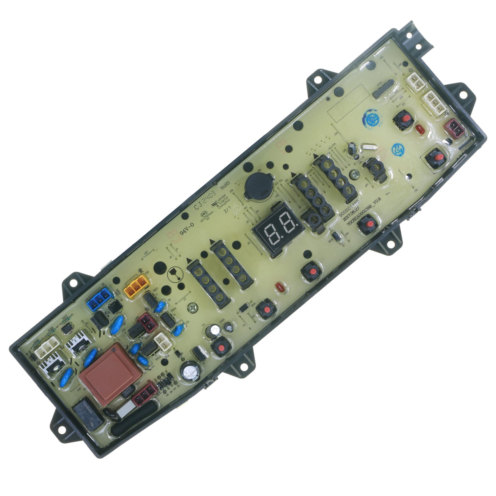
W11176140 Top-Load Washer Electronic Control Board
Cross-Reference / Replaces: W11035628, W11088499, W11116590, 4547033, AP6285514, PS12347313, EAP12347313.
Guaranteed Fit: Whirlpool WTW5000DW, WTW4950HW, WTW4815EW, Maytag MVWC565FW, MVWC465GW, and Kenmore 110.22352511 series washers.
- ✓ 365-Day Return Guarantee
- ✓ Pre-Programmed OEM Logic
- ✓ 1-Year Comprehensive Replacement Warranty
5. Step-by-Step Replacement Instructions
Required Tools
- 1/4-inch hex nut driver or socket
- Stiff putty knife (plastic or taped metal)
- Smartphone (to photograph wiring harness pin assignments)
Slide a stiff putty knife horizontally between the bottom edge of the control console and the top panel, approximately 6 inches in from each side. Push backward firmly to depress spring clips while lifting the console upward.
Pivot the console assembly up and back to reveal the internal plastic protective cover shielding the main control board.
Take a clear reference photograph of the wiring harness layout. Disconnect each edge connector by depressing the center locking tabs.
Gently twist and pull the clear vinyl pressure sensor tube off the old control board transducer nipple.
Depress mounting bracket tabs and unseat the old board. Seat the replacement W11176140 PCB until all retaining clips snap over edges. Reattach the clear pressure sensor tube firmly.
Reconnect all multi-pin harness plugs using your reference photograph. Lower the console back onto the top panel and press down until both metal spring clips lock into place.
6. Mandatory Post-Installation Calibration Cycle
- Reconnect power and water. Ensure washer tub is completely empty.
- Enter Service Diagnostic Mode (1 click CCW, 3 clicks CW, 1 click CCW, 1 click CW).
- Turn cycle knob clockwise until only the RINSE status LED is illuminated (Calibration Mode).
- Press START. The washer will automatically lock the lid, energize water valves briefly, and spin through calibration for 2–4 minutes until all LEDs extinguish.