
Understanding LBP, MBP, and HBP in Refrigeration Compressors: Technical Definitions, Operational Envelopes & Selection Logic
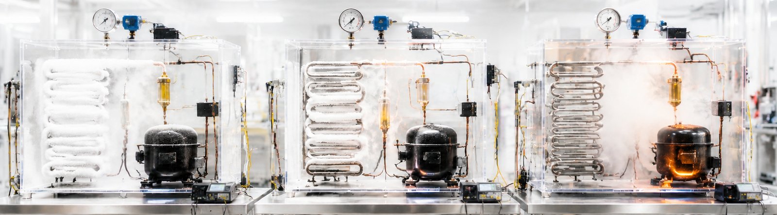
Understanding LBP, MBP, and HBP in Refrigeration Compressors: Technical Definitions, Operational Envelopes & Selection Logic
Executive Technical Summary
In refrigeration engineering, the acronyms LBP (Low Back Pressure), MBP (Medium Back Pressure), and HBP (High Back Pressure) define the operational evaporating temperature envelope and suction vapor density a hermetic compressor is mechanically and electrically engineered to handle. Compressor horsepower (HP) alone is never an adequate selection metric. Because refrigerant vapor density increases dramatically with rising suction pressure, motor displacement, electric motor torque, valve port geometry, and suction-gas cooling pathways are fundamentally optimized for each specific pressure regime. Substituting an incorrect pressure classification causes catastrophic motor burnout or severe capacity loss.
1. Technical Definitions & Operational Temperature Envelopes
The term "back pressure" refers to the suction pressure entering the compressor crankcase from the evaporator line. Suction pressure directly dictates the saturated evaporating temperature (SST) of the circulating refrigerant.
| Classification | Full Technical Name | Approved Evaporating Range | Typical Equipment Application |
|---|---|---|---|
| LBP | Low Back Pressure | -35°C to -10°C (-31°F to +14°F) | Domestic freezers, ice makers, commercial reach-in deep freezers, ice cream hardening cabinets. |
| MBP | Medium Back Pressure | -20°C to 0°C (-4°F to +32°F) | Commercial glass-door bottle coolers, deli counters, dairy display cases, walk-in cold rooms. |
| HMBP | High-Medium Back Pressure | -25°C to +10°C (-13°F to +50°F) | Extended-envelope commercial coolers, batch ice machines, multi-compartment refrigerators. |
| HBP | High Back Pressure | -5°C to +15°C (+23°F to +59°F) | Liquid water chillers, residential air conditioning, dehumidifiers, compressed air driers. |
| AC | Air Conditioning Dedicated | 0°C to +15°C (+32°F to +59°F) | Central air conditioners, heat pumps, comfort cooling systems. |
2. Standard Rating Test Conditions (ASHRAE vs. CECOMAF)
Compressor capacity ratings (expressed in BTU/h or Watts) cannot be compared directly without referencing the rating standard. The two globally dominant rating protocols are ASHRAE (North America) and CECOMAF (Europe):
| Standard | Classification | Evaporating Temp | Condensing Temp | Ambient Temp | Suction Gas Temp | Subcooled Liquid |
|---|---|---|---|---|---|---|
| ASHRAE | LBP | -23.3°C (-10°F) | +54.4°C (+130°F) | +32.2°C (+90°F) | +32.2°C (+90°F) | +32.2°C (+90°F) |
| CECOMAF | LBP | -25.0°C (-13°F) | +55.0°C (+131°F) | +32.0°C (+89.6°F) | +32.0°C (+89.6°F) | +55.0°C (+131°F) |
| ASHRAE | MBP | -6.7°C (+20°F) | +54.4°C (+130°F) | +35.0°C (+95°F) | +35.0°C (+95°F) | +46.1°C (+115°F) |
| CECOMAF | MBP | -10.0°C (+14°F) | +55.0°C (+131°F) | +32.0°C (+89.6°F) | +32.0°C (+89.6°F) | +55.0°C (+131°F) |
| ASHRAE | HBP | +7.2°C (+45°F) | +54.4°C (+130°F) | +35.0°C (+95°F) | +35.0°C (+95°F) | +46.1°C (+115°F) |
| CECOMAF | HBP | +5.0°C (+41°F) | +55.0°C (+131°F) | +32.0°C (+89.6°F) | +32.0°C (+89.6°F) | +55.0°C (+131°F) |
3. Thermodynamic, Displacement & Motor Torque Engineering Dynamics
Why can't one universal compressor cover all temperature ranges? The answer lies in the fundamental relationship between suction vapor density, mass flow rate, and motor work:
Core Engineering Differences Between LBP and HBP Compressors
- Suction Vapor Density & Mass Flow: At -30°C (-22°F), refrigerant vapor is sparse with a low specific density. At +7.2°C (+45°F), the suction vapor density of the same refrigerant is 3x to 5x higher. High density means every stroke of the piston moves significantly more mass of refrigerant.
- Cylinder Displacement vs. Motor Horsepower:
- LBP Compressors: Feature a larger displacement cylinder paired with a lower-power electric motor. Because the low-density vapor creates relatively low mechanical compression resistance, a smaller motor can drive a large displacement piston.
- HBP Compressors: Feature a smaller displacement cylinder paired with a heavy-duty, high-torque electric motor. Compressing dense suction vapor requires massive mechanical force per revolution.
- Compression Ratio: LBP systems operate at high compression ratios (typically 10:1 to 15:1), requiring tighter piston tolerances and optimized re-expansion clearance volume. HBP systems operate at low compression ratios (2.5:1 to 4:1).
- Motor Cooling Mechanism: In hermetic compressors, returning suction vapor flows over the internal stator windings to remove heat. In LBP operation, the mass flow rate is very low; motors must be engineered for higher thermal resilience, or auxiliary oil cooling tubes / condenser fans must be utilized.
4. Catastrophic Failure Modes of Application Mismatch
Installing a compressor outside its designated back pressure envelope will result in predictable, rapid mechanical or electrical failure.
| Substitution Error | Thermodynamic & Electrical Consequence | Final Equipment Failure Mode |
|---|---|---|
| Installing an LBP Compressor in an HBP/MBP Application (e.g. Putting a freezer compressor on a beverage cooler or dehumidifier) | High suction pressure delivers dense vapor into a large displacement cylinder. The light-duty LBP motor lacks sufficient torque to compress this high mass flow. Motor current spikes drastically above rated running load amps (RLA). | Motor Burnout: Compressor repeatedly trips on thermal overload protector within minutes. Stator windings overheat, breaking down insulation, carbonizing oil, and shorting the motor within hours or days. |
| Installing an HBP Compressor in an LBP Application (e.g. Putting an A/C or cooler compressor on a deep freezer) | Low evaporating pressure produces very thin vapor. The small displacement cylinder of the HBP compressor cannot move enough mass flow to generate adequate refrigeration effect. | Insufficient Freezing & Thermal Breakdown: Freezer fails to pull down below 10°F (-12°C). Extremely low mass flow deprives the motor of suction cooling, leading to high discharge temperatures and oil sludge breakdown. |
5. Motor Starting Torque Configurations (LST vs. HST)
In addition to back pressure classifications, compressors are paired with specific motor starting systems depending on the metering/expansion device used in the sealed system:
| Starting Torque | Motor Electrical Type | Expansion Device Pairing | Operating Principle |
|---|---|---|---|
| LST (Low Starting Torque) | RSIR (Resistive Start Induction Run) RSCR (Resistive Start Capacitor Run) | Capillary Tube (Fixed Restrictor) | Pressures equalize across the capillary tube during the off-cycle. The compressor starts against zero pressure differential, requiring low starting torque. |
| HST (High Starting Torque) | CSIR (Capacitor Start Induction Run) CSR (Capacitor Start and Run) | TXV / EEV (Thermostatic / Electronic Expansion Valve) | Expansion valves maintain high head pressure and low suction pressure during off-cycles. The motor requires high starting torque (via start capacitor & potential relay) to start against severe differential pressure. |
| Variable Speed (Inverter Driven) | BLDC / PMSM (Brushless DC 3-Phase Variable Frequency) | Capillary Tube or EEV | Driven by an external frequency inverter (e.g. Embraco VCC3). High starting torque delivered electronically via soft-start ramp control. |
6. Step-by-Step Compressor Selection Protocol for Technicians
When selecting a replacement compressor for any refrigeration or cooling equipment, follow this rigorous 5-step engineering verification protocol:
Compressor Selection Protocol Checklist
- Step 1: Identify Operating Evaporating Temperature (SST):
- Freezing (-35°C to -10°C) → Select LBP.
- Chilled Storage / Beverage (-20°C to 0°C) → Select MBP or L/MBP.
- Dehumidification / Air Conditioning (-5°C to +15°C) → Select HBP or AC.
- Step 2: Confirm Sealed System Refrigerant:
Verify the refrigerant chemical family on the appliance rating plate (R-600a, R-134a, R-290, R-404A, R-410A, R-32, R-454B). Never charge mineral oil compressors with HFC/HFO refrigerants, and never use POE oil compressors on pure HC systems without manufacturer approval. - Step 3: Match Refrigeration Capacity at Standard Rating Point:
Do not size by nominal Horsepower (HP). Match cooling capacity in BTU/h or Watts at the specific standard evaporating temperature (e.g., -23.3°C for LBP, +7.2°C for HBP). - Step 4: Check Metering Device & Starting Torque:
If the system utilizes a TXV expansion valve, verify the replacement compressor has HST motor electrics (start capacitor + relay). - Step 5: Verify Electrical Voltage, Frequency & Physical Footprint:
Confirm line voltage (115V 60Hz, 208-230V 60Hz, or 3-Phase Inverter) and verify suction/discharge copper pipe diameters and mounting base grommet spacing.
7. Equipment Application Quick Reference Matrix
| Equipment Type | Pressure Class | Typical Target Temp | Dominant Refrigerant | Expansion Type | Torque Type |
|---|---|---|---|---|---|
| Household Refrigerator-Freezer | LBP | 0°F to 37°F (-18°C / +3°C) | R-600a / R-134a | Capillary Tube | LST (RSCR) / Inverter BLDC |
| Commercial Standalone Deep Freezer | LBP | -10°F to 0°F (-23°C / -18°C) | R-290 / R-404A | Capillary / TXV | HST (CSIR / CSR) |
| Glass Door Beverage Merchandiser | MBP | 34°F to 38°F (+1°C / +3°C) | R-290 / R-134a | Capillary Tube | LST (RSIR) or HST |
| Commercial Deli & Meat Display Case | MBP / HMBP | 28°F to 34°F (-2°C / +1°C) | R-290 / R-448A | TXV Valve | HST (CSIR / CSR) |
| Residential Dehumidifier | HBP | 45°F to 65°F (+7°C / +18°C) | R-32 / R-134a / R-290 | Capillary Tube | LST / PSC Motor |
| Central Air Conditioner & Heat Pump | HBP / AC | 45°F to 55°F (+7°C / +13°C) | R-454B / R-32 / R-410A | TXV / EEV | HST / Inverter Scroll |
Appliance Technical Desk & Part Verification
Compressor Cross-Reference
Send a photo of your compressor rating label for direct displacement & capacity matching.
OEM Inverter & Control Modules
Browse factory pre-calibrated variable frequency compressor drives.
365-Day Return Guarantee
Factory-certified replacement parts backed by comprehensive technical warranty coverage.